 353 West Grove Ave. Orange, California 92865
1. Power System Compatibility
The Micro-meter can work with both single-phase and three-phase electrical systems, as long as they are within the supported voltage ranges.
Single-phase (50 or 60 Hz)
- 110-120 V AC
- 208-220 V AC
- 277 V AC (voltage from Neutral to one phase in a 480 V three-phase "Y" system)
- 480 V AC phase to phase
Three-phase (50 or 60 Hz)
- 208 V AC in a Y-network with Neutral
- 240 V AC in a Delta network
- 480 V AC in Y-network with Neutral
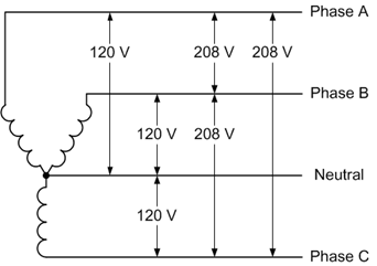
Fig 1. Three Phase, four-wire 120/208 Wye Connection
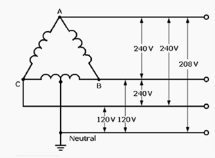
Fig 2. Three Phase, four-wire 120/240 Delta Connection
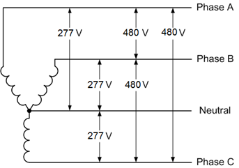
Fig 3. Three Phase, four-wire 277/480 Y Connection
2. Relay Output Function for Demand Response application
The Micro-meter contains a relay that acts like a remote-controlled on/off switch - but it is only meant to control the coil of a contactor, not to directly power heavy machinery.
- The relay terminals are labeled T1 and T2 on connector J3.
- By default, these two terminals are open circuit (like a switch in the "OFF" position).
- When the Micro-meter activates the relay or activating the demand response, the connection closes (like turning the switch "ON").
Isolation: The relay is fully isolated from the high-power lines that the contactor controls. The Micro-meter never handles the heavy load current directly.
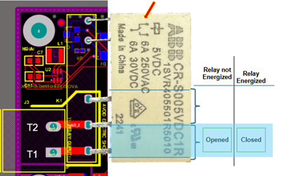
Fig. 4. Relay Connections
The J3 relay output itself does not "produce" a voltage - it is simply an open/close switch. The user supplies the voltage for the contactor coil, which can be:
- 24 V
- 110/120 V
- 208/230 V
- 240 V (As long as it's 250 V or below, it's acceptable.)
3. Current Transformer Input
The Micro-meter's current transformer input range is from **0 Amps to 50 Amps** (0-50A). This means it can accurately measure current levels within that range from the connected transformer.
4. Suggested Contactors & Wiring
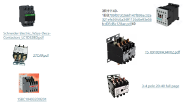
Fig. 5. Suggested Contactors to use with Micro-meter
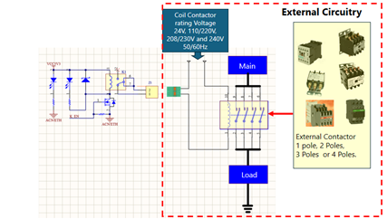
Fig. 6. Suggested connection of Contactors to Micro-meter
5. Installation Instructions
The most up-to-date installation instructions are on the micro-meter.com website. These instructions will guide the user step-by-step on how to properly install the Micro-meter according to the latest standards and requirements.